Options for Physical Lockout Measures
Physical lockout measures are the first and most effective line of defense against unintentional re‑energization. They ensure that a system cannot be mechanically put back into operation while work is being carried out.
🔒 Personal Locks
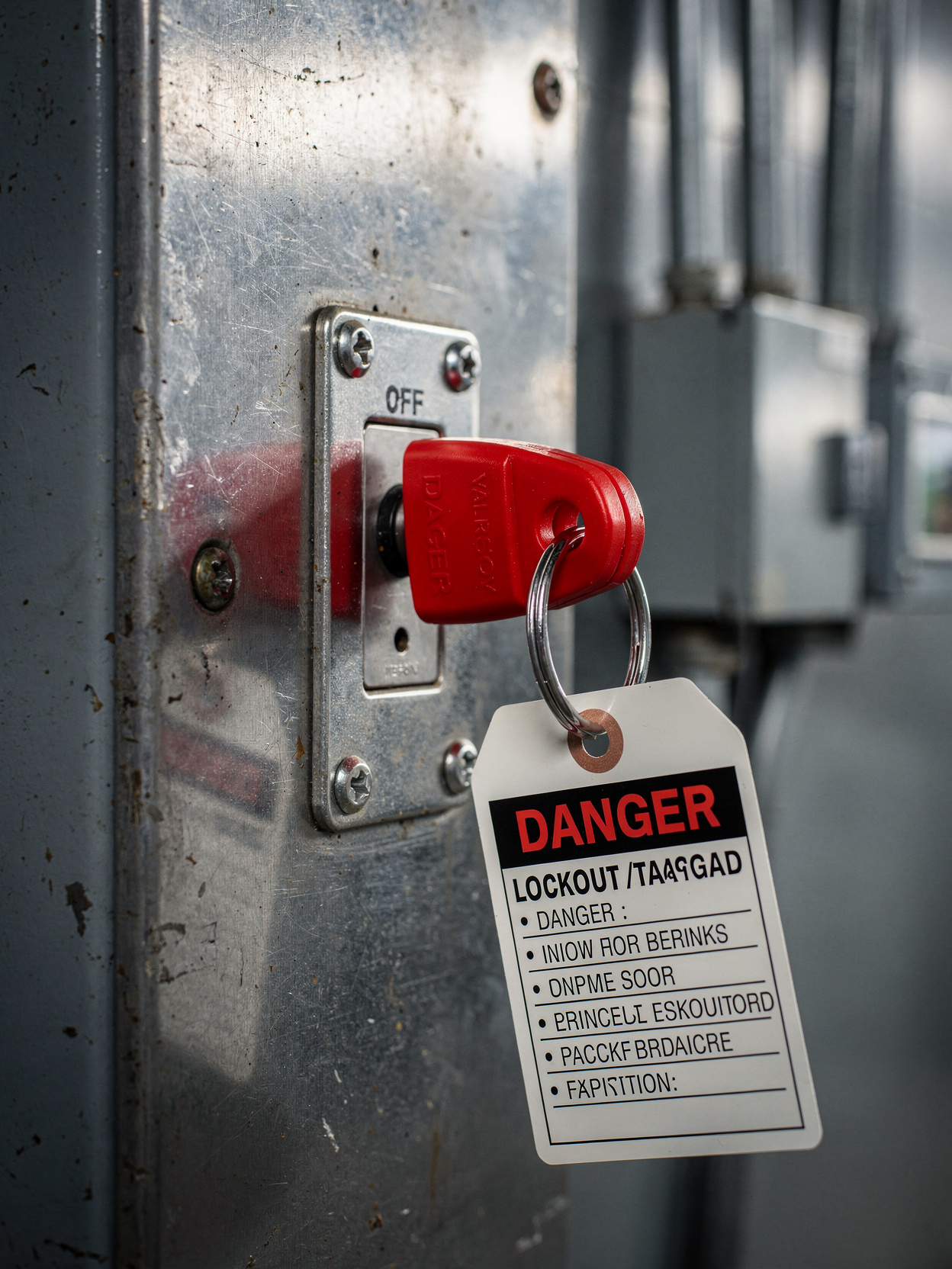
Personal locks are attached directly to the disconnecting device – only the responsible employee has the key.
🔌 Plug Stops
Special plug‑blocking devices prevent a plug from being inserted into a locked socket.
📦 Disconnect Boxes
Service disconnect units are locked and sealed so that the high‑voltage connection remains physically interrupted.
🔑 Main Switches
Central main switches are secured with lock cylinders to prevent unauthorized operation.
Organizational Safeguards
Technical measures alone are not enough. Organizational processes create clear responsibilities and ensure that all involved persons are informed and protected.
Warning Tags (Tagging)
Highly visible signs and tags on the switching device clearly indicate the lockout status to everyone in the work area.
Documentation of the Shutdown
Checklists and digital logs record every switching operation and provide legally compliant proof of the measures taken.
Lockout Supervisor
A designated responsible person oversees the entire lockout process and coordinates all involved employees.
Zone Security
Access restrictions for the entire work area prevent unauthorized persons from entering the danger zone.
Technical Aids
Modern technical aids support safe handling of high‑voltage systems and effectively complement physical and organizational measures.
Keyed‑Alike Lock Systems
For complex systems with multiple disconnect points, keyed‑alike locks enable coordinated and seamless lockout of all points.
LED Status Indicators
Visual indicators provide instant information about the current operating state – green for safe, red for locked.
Mechanical Plug Locks
Special attachments physically prevent a plug from being inserted – even accidental attempts cannot re‑energize the system.
Insulated Tools & PPE
Tools and personal protective equipment compliant with DIN EN 60900 form the final protective layer when working directly on HV components.
Responsibilities
Who is Responsible?
Clear assignment of responsibilities is essential. Every person involved must know their role and be able to prove the required qualifications.
Unclear responsibilities are one of the most common causes of workplace accidents involving high‑voltage systems.
High‑Voltage Qualified Person (FHV)
Assesses specific hazards and defines appropriate protective measures for the respective work task.
High‑Voltage Coordinator
Defines and monitors internal protective measures and ensures compliance with all regulations.
Training
Regular and documented instruction of all involved employees – at least once per year.
Qualified Measurement Personnel
Measurements to verify absence of voltage may only be performed by demonstrably qualified personnel.
Practical Example: The LTCT Principle
The LTCT principle describes a proven four‑step procedure for safely de‑energizing high‑voltage systems. It is internationally recognized and forms the basis of many operational lockout procedures.
🔴 Lockout
Switch off – the system is de‑energized and physically disconnected from the power source.
🏷️ Tag
Mark – warning signs and locks are applied to communicate the lockout status.
✅ Clear
Verify – the work area is checked, stored energy is discharged, and absence of voltage is measured.
🔬 Test
Secure – final verification of all protective measures before work begins.
Clear visual instructions directly at the switches and unambiguous labeling of all components reduce the risk of confusion to an absolute minimum.
Error Prevention in the Workshop
Even experienced professionals can make dangerous mistakes due to routine or time pressure. The following points are the most common sources of error and must be actively addressed.
Never Rely on the Plug Alone
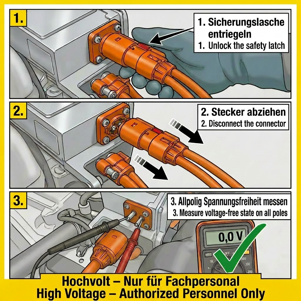
Simply unplugging the HV connector is not considered sufficient lockout. Always use additional blocking devices.
Document Absence of Voltage
Measured absence of voltage must be documented in writing – this serves as legal proof in case of damage.
Consider Stored Energy
Capacitors may still hold dangerous voltages after shutdown. Always observe discharge times and verify.
Active Communication
All persons in the work area must be informed about the lockout status – verbally, in writing, and through visible labeling.
Documentation and Proof Requirements
Complete documentation is not only a legal obligation but also protects employees and the company. Every safety‑relevant event must be traceable.
Logging Every Action
Date, time, involved persons, and measures taken are recorded for every lockout.
Archiving Hazard Assessments
Vehicle‑specific hazard assessments must be complete and up to date.
Updating Work Instructions
New HV systems and vehicle architectures require regular updates of all relevant instructions and checklists.
Conclusion: Safety Through Consistency
Safety is not a state – it is an active, daily practice.
🔗 Combination is Key
Only the consistent combination of technical disconnection, physical lockout, and organizational safeguards saves lives.
📋 Documentation as Protection
Complete and up‑to‑date documentation is the final, indispensable step toward safe work on HV systems.
🔄 Continuous Improvement
Regular training, updated work instructions, and open communication keep the safety level consistently high.